Ode to Ribbon Cables
My undying love for IDC flat cables.
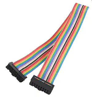
ribbon

Ode to Ribbon Cables

The ubiquitous IDC (Insulation Displacement Cable) ribbon cables have been used since the 70's. Ribbon cables were used with many early PC interfaces: IDE, Floppy, RS232, SCSI, Printer, LCDs, you name it. Ribbon cables can be used in many applications from audio, Eurorack module power, control, whatever.

Compared to crimp-and-poke, the number of operations and therefore the time to assemble a cable is soooo much faster. Hell is building a 40 pin crimp-and-poke cable with hand tools. The deepest level of hell is building a handful of them.

High Speed Digital and Critical Analog

For high speed digital or critical analog, one method to maintain signal integrity, minimize crosstalk and EMI is to use interleaved grounds, and to terminate the far end, typically with a 220/330 ohm pull-up/down resistor network. This works well up to about 50 MHz. Another method is to use shielded cables, but these can be tricky to terminate the shields. A third is to use differential signaling, and to terminate with a 110 ohm differential resistor. A fourth is to use lower voltage signaling such as ECL or LVDS. With these you can exceed 100MHz and keep EMI to a minimum.

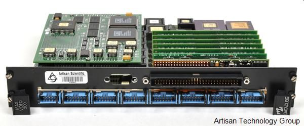
At Datacube in the 80's and 90's, we needed a way to route 8-bit image data from VME board to board. And way to synchronize the clocks across 2 to 100 boards. For the data, we used TTL / CMOS 5V signals over multiple 14 pin ribbon cables. For the clocks we used a 10 pin ribbon cable with differential 40 MHz PECL clocks. It was driven at one end, had multiple PECL recievers along the wire, and terminated at the far end. This was called MaxBus and was the original standard for Datacube pipelined image processing systems. We built dozens of imaging products based on this "standard" that I designed. Here is a MaxVideo 200 imaging system showing the MaxBus ribbon cable connections for expansion to additional modules.
mv200

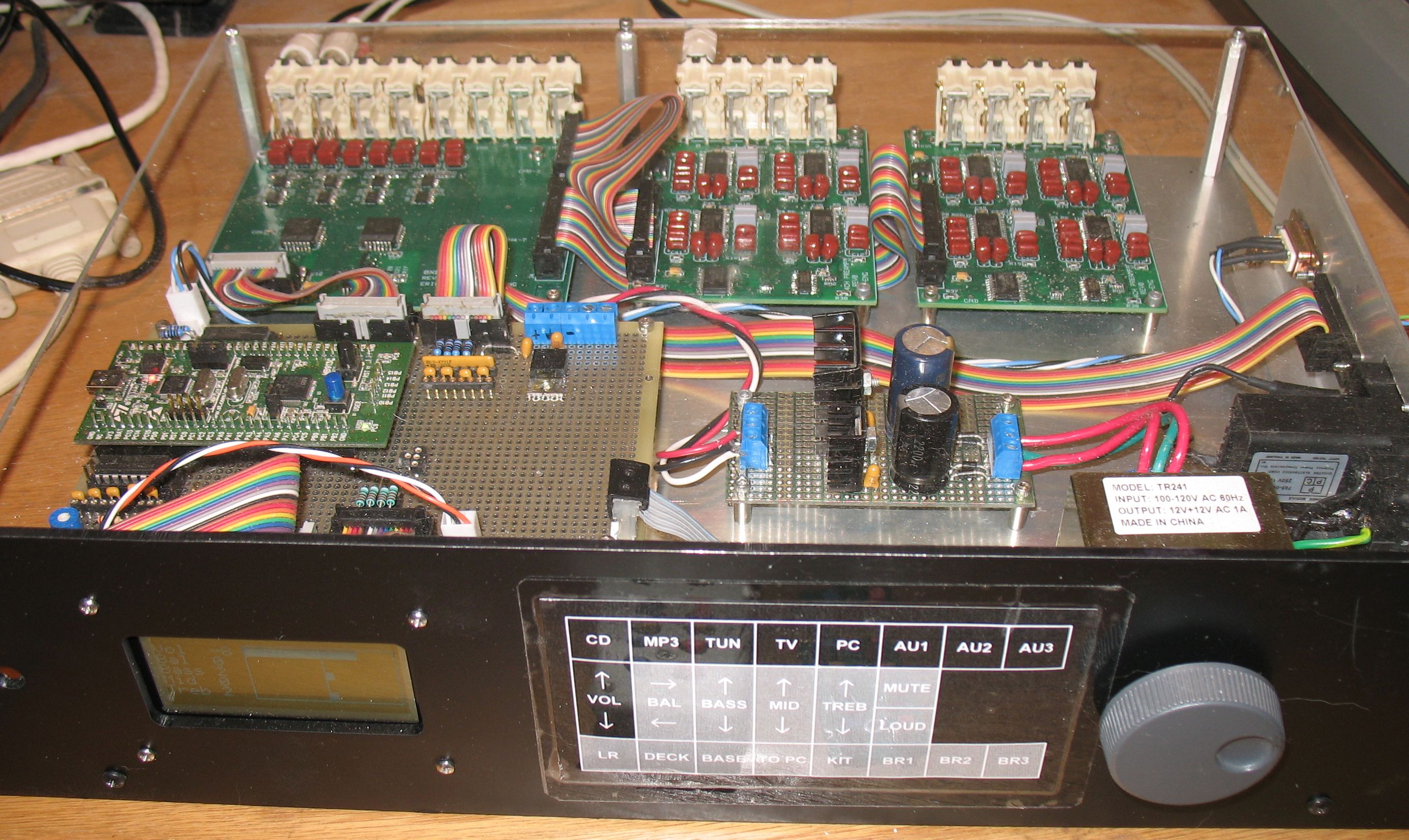
I have used ribbon cables for critical audio connections by simply interleaving signals and grounds. This reduces crosstalk to very low levels and provides high integrity grounding between boards. Here is my Multizone, Whole-House audio system with ribbon cables used to connect power, multi-channel audio and I2C between the boards.

  multizon

This table shows the parameters of various interconnect methods for comparison.
Parameter
Ribbon cable
Molex KK/ Amp MTA
Hirose DF13
Flat Flexible Cables
Pitch
0.050" or 1mm
0.1"
1.25mm
0.5-1mm
Length
Any
Any
Any
Up to ~1m
Pin count
6-64
2-12
2-20
10-60
Wire size
28AWG
28-22 AWG
26AWG
.3 x .15mm copper
Cost / pin (parts)
~$0.10
~$0.40
$0.20

Cable assembly labor
Minimal: cut cable to length and 2 press operations
2 crimps and 2 pokes per pin
2 crimps and 2 pokes per pin None
Board terminations
TH, SMT, 2 row headers (box, ejector or bare)
1 row headers
SMT and TH

Other connectors
D-Sub, DIP, wire-to-board, bare wire
Bare wire, other crimp-and-poke
Bare wire, other crimp-and-poke None
Board area / pin
0.1-0.2 sq in
0.3 sq in
~0.05 sq in
~0.03 sq in
Keying
Yes
Optional
Yes
Yes
Tooling
Simple press handles all sizes
$10-500 manual crimp tool
$1000 manual crimp tool
None

I like the standard 0.050" pitch types. Connectors and cables are low cost. Connectors are available in common sizes from 6 to 64 pins.

I like that the cables are quick and easy to build. Y
ou simply cut the cable to length, and squeeze the connector on, in one simple operation, as opposed to cut, strip and crimp both ends of each wire, then poke. Lots can go wrong with crimp-and-poke.  Building crimp-and-poke cables is soooo slow.

I like their reliability.
In the old days we used only T&B connectors because they were the highest reliability, using better crimp connections. Nowadays it seems that even the cheapest Chinese Ribbon Cable connectors are quite reliable. Contacts are selective-gold-plated to minimize oxidation failures.

I like that these are 2 row connectors so board density is pretty good, more than 2x the density of Molex KK. I like that implementing interleaved grounds is easy.

For male PCB connectors, I try to use "Box" headers. These are slightly larger than bare a 2-row header, but are keyed to prevent incorrect installation. I always use the keyed female connectors. Better to have the key and not need it then to need the key and not have it.

I like that you can get optional retention / ejection handles on the male connectors, but they require extra board real-estate. At Datacube we used the smaller vertical ejectors built by T&B. If your system is subject to significant shock and vibration, you should use the retainers. This includes shipping. I was always encouraged by PC manufacturers not using retainers and having good enough reliability. Maybe a cable would occasionally fall off inside a PC from shipping. Your choice.

I like that you can get an added strain relief for slightly higher cost and higher connector height. If you need to repeatedly plug and unplug cables, strain relief is a good idea. Also for high-reliability systems.

I like that you can add intermediate connectors to a cable, thus building a bussed system to connect more than 2 boards together. This is good for I2C and some SPI systems. This method is also used for powering some Eurorack systems.

I like that other connectors are available in 0.050"  IDC:  Male headers, D-Sub, direct board to wire, DIP plugs, and others.  The male headers allow you to build extender cables. The DIP plugs are really handy for plugging cables into existing systems, such as for emulators. Ribbon cable D connectors are typically expensive. This is because D-Sub pin pitch is not 0.050". Each pin in the connector needs a unique bend to adapt to the 0.050 cable pitch.

I like that you can take a wide cable and separate out narrower cables very easily. So for prototyping, no need to buy all different sizes.

I like that you can separate the strands in the middle of a cable with an exacto knife to convert from flat to round. This can be helpful for routing a cable through smalller holes, or just adding more flex to a cable.

If you want to separate the conductor strands into individual wires, this can be done easily.  You can get boring grey cable, or festive rainbow colored cable. The rainbow cable is great if you need to separate the strands. Color coding makes it much easier to separate and identify the individual wires.

0.1" dual-row headers can't be used on a proto-breadboard. but are grid-board friendly. If you need something smaller, the 1mm pitch cables are available. I have not used them, and they won't work on grid-boards.

In the old days, wire-wrap versions with longer pins were more available. Not really a concern any more.

IDC Compatible Crimp-and-poke

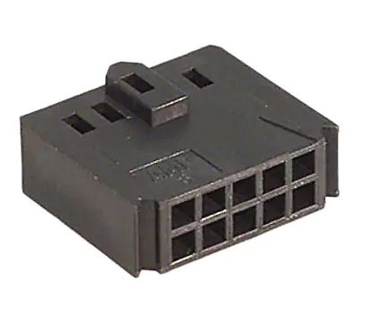
Sometimes you need a female crimp and poke style connector that can be plugged into a male ribbon cable connector. This requires a compatible polarity key and some extra plastic on the ends. Check out the Amp Ampmodu Mod IV connectors. The 10 pin one is 102387-1.
amp

Hirose DF13

The downside of Ribbon cables is that they are large. There are many smaller options. At my most recent day job, we chose Hirose DF13's for internal wiring. These are small, 1.25mm pitch Crimp-and-poke connectors. Their reliability has been very good. The cable Contract manufacturers that built our cable assemblies know how to do proper and reliable crimps. You can buy pre-cut and crimped DF13 wires from Digikey and others. The hand-crimp tool for DF13 is expensive, like $800.

Molex KK / Amp MTA

I still use a lot of Molex KK  0.1" and 0.156" connectors. Particularly for low pin count cables, typically 2-6 pins. The larger 0.156 connectors are used for high current and voltages, AC line voltage,  Here is my web page on their use and issues.


The Blog for this project (not yet)
  Dave's Home Page

Last Updated: 9/23/2022