DIY Synth Page 1:
Analog
Analog Synthesizer in Eurorack format
The Blog
for this project
The Schematics, PCB files, and Simulation
models are here
Page 2: the Digital part
Page 3: OLEDs and
CV-> Midi
I have you, Steve to
thank (blame) for this latest obsession. OK, you and the
world-wide resurgence of interest in Analog Synthesizers, combined
with my love of analog designs and music. In the mid 70's an
old friend Jeff, a very smart analog engineer, designed and built
an analog synthesizer from scratch. It was a modular, and had most
of the features you would expect. I played with it a bit, not
much. Fast forward 40 years, and the world has re-discovered these
things. Moogs and Arps sell for many times over their original
prices.
I put this off for a while because I had little to offer the synth
community. In fact, most of the circuits were designed 40-50 years
ago and have been refined ever since. One big problem with old
synths and their designs is that the opamps, transistors and other
components used to build the original machines have long gone
obsolete. Originals and replacements are old stock only and sell
for top dollar. Meanwhile, there are few surface mount designs.
Surface mount offers smaller, more modern and thus available
parts, and machine assembly as well as hand assembly. As a
pro-fessional 'lectical engineer, I almost never design with
thru-hole technology. Even my test boards and one-offs use
SMT. The small size offers lower parisitics and thus closer to
theoretical performance. Not so much an issue with audio
frequencies, but it doesn't hurt. I find it easier to mount and
solder a part on one side instead of bending the leads, mounting
it through the board, bending the leads again to hold the
component in place, soldering it through the board, flipping the
board, soldering the leads on the rear, then trimming the leads.
It's not so bad, but how 70's.
Here is one example: do a Digikey search for 'matched NPN' then
filter by SMT and by thru-hole. There are two old and expensive
part numbers in thru-hole and a couple dozen in SMT including the
precision SSM and MAT series from Analog Devices. Some SMT parts
that are matched to better than 2mV are less than $.50. No more
hand matching and gluing together transistors. Thank you, modern
technology.
There are many modular synth systems, starting with the Moog
Modular and others from the '60s. The current rage is Eurorack 3U.
An amazing assortment of Eurorack modules are available in kit,
board or completed form. The Eurorack platform is very simple, a
16 pin ribbon cable backplane provides power and a couple of
bussed control signals. Mechanically, each module needs only a
flat front panel and a few screws. The card cages use standard
hardware, and are strong, flexible, low-cost and available.
The concept of modular solutions has always appealed to me. When I
was at WPI in the early 70s, I learned to simulate physical
systems on Analog Computers. Yes, I am that old. In the 80's at
Datacube I was one of the inventors of generations of MaxVideo
modular image processing systems. At Analogic and Teradyne, we
developed modular instrumentation for PXI, VXI and several
proprietary platforms. At home I worked on modular solutions for
microprocessor development and for low cost instrumentation
solutions, but these never got off the ground.
One appeal of Eurorack is its utter simplicity. Each module is
sheet metal, a circuit board or two, a ribbon cable, some
knobs and jacks, and the creativity you bring. I love it.
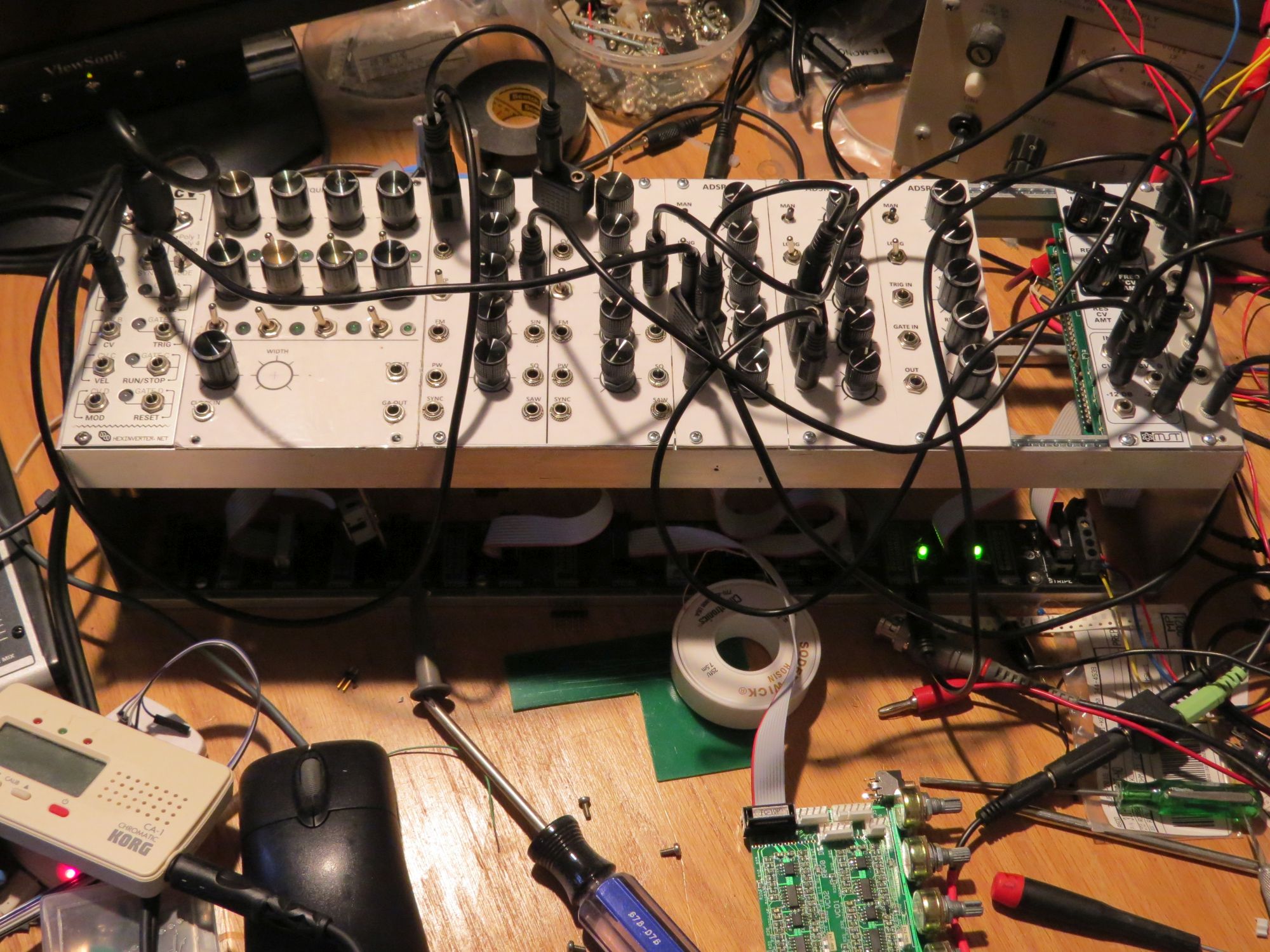
Here is my first pass synth system on the electronic work bench,
in all its wiry glory. From Left to Right: MIDI2CV,
Sequencer prototype, Dual VCO, three ADSRs, VC-LPF, and a passive
Mixer. It is beginning to look like a synth, but still has a
science experiment look.
VCO
I wanted to get started
with some existing technology and to gain some experience with the
basic mechanical components, pots, jacks, switches, etc, as well
as with building and packaging. I looked for VCO, VCA, VCF, and
ADSR designs that I could lay out in SMT, and that would give me
full function quality electronics. The VCO is one challenge. Since
it is the heart of any synth, it needs to be flexible. Accurate
voltage control, manual pitch, FM, and voltage control over
parameters such as pulse width are all useful functions found in
most full-featured VCOs. Waveforms should include all the basics:
Sine, Triangle, Ramp and Pulse. It needs to be stable with
temperature and time so that continuous tuning is not required.
Most VCOs use an exponential voltage to current circuit that was
originally published by National Semi in the '60s. The 'standard'
for voltage control is 1 volt per octave (1V/O) and it needs to
operate over the audio range of about 20Hz to 20KHz, or about 10
octaves. Stated as 1000:1 it sounds easier. Most designs use the
exponential current source to charge a capacitor, typically until
it reaches a threshold, then the capacitor is discharged. Charge
and discharge the cap at the same current but opposite polarity,
and you get a triangle wave. Discharge it quickly and you get a
ramp, AKA sawtooth or saw.
A ramp can be converted to a triangle using
full-wave-rectification, also known as the absolute value
function. A triangle can be converted to a sine with a non-linear
circuit, and a triangle or ramp can be converted to to a square
wave or varying pulse width via a comparator.
Turns out a triangle can be converted to a ramp using an
inverting-non-inverting circuit. So the question is, which
waveform to begin with, a ramp or a triangle? There are numerous
examples of both. Converting a ramp to a triangle is harder than
it looks. The fast rise-time of the ramp causes a fast glitch on
one peak of the triangle, which causes unwanted harmonics. This
glitch will show up on sine waves derived from the triangle. Just
what you don't want on triangles and sines: harmonics. I
have seen circuits with two trimpots to try to null out the glitch
but that seems like a hack. So I decided to start with a nice
mellow triangle, and then use a fast switch to add the fast
transients that a ramp needs. I came up with the idea of
using a current mirror to invert the current, and CMOS switches or
transistors to route the currents.
It also turns out that the symmetry of a triangle works better
than a ramp when operating at high frequencies. A ramp's capacitor
discharge takes a finite amount of time, and that time is added to
the desired ramp period, causing an error in frequency that gets
worse at higher frequencies. To fix this, most VCOs have a high
frequency adjustment which is not a simple adjustment to make.
With a triangle, the time to switch direction is due to a
comparator and a flip-flop, generally faster than a transistor
discharging a cap. I haven't implemented a high frequency trim
yet, and the VCOs work well without it. Also if my 10KHz is a bit
off, who will know? Most dogs don't have perfect pitch. That was
the theory, and the Spice simulation agreed. When I built an
dtested four of these VCOs, I found that the high frequency
linearity was excellent up to 16KHz. If anything, the oscillator
was a bit sharp (too high frequency) at 16KHz, or about C6,
without any compensation trim. Good enough. I suspect this is an
advantage to the triangle VCO design vs. a ramp design.
For the control logic, I pictured something akin to a 555 timer. A
555 compares a voltage (usually on a capacitor) to 1/3 and 2/3 of
the power supply voltage, and sets or resets a flip-flop. It is
basically a triangle and square wave generator. I did a google
search for triangle VCO and came up with Ian Fritz page. His
schematic for the triangle VCO looks a lot like my pencil block
diagram. http://home.comcast.net/~ijfritz/sy_over.htm
He uses a "Wilson current mirror" and CMOS switches to get the
current inversion accuracy and symmetry, and used a couple of
comparators and CMOS switches to replace the flip-flop. His design
is nice but uses kind-of a lot of parts. Bergfoton also has a
transistor based Triangle VCO here.
Again, kind of a lot of parts and trims.
Then I thought of using an OTA, the LM13700 as the switchable
polarity current switch. These operate over 5 or more decades of
current, and I only need 3-4. I googled "triangle VCO with
LM13700" and found Thomas Henry's excellent "555-VCO" on
Muffwiggler. This is just what I had in mind. The core oscillator
is half of an LM13700, a buffer amp for the triangle, and a 555
timer. No symmetry trimpots, and minimum component count.
Then he cleverly uses the Reset pin of the 555 as a VCO 'SYNC'
input, and the TRIG output to switch the gain of the ramp
generator. Very clever design using all the features of the little
555. To convert the triangle to a ramp, he uses the 555 trigger
output to switch the polarity of an op-amp. I thought this was
pretty genius, however a few weeks later I was perusing some old
1960's EML synthesizer schematics to see how their VCOs worked,
and there was the same triangle to ramp circuit using the same
inverting/non-inverting circuit. Many good ideas have been
around for a long time.
Thomas published his design and offered PC board builds including
a Eurorack front panel for short money. Unfortunately I missed his
buying window. Besides I'd like to lay out and build the boards
myself. I looked in my basement and found a couple of ancient
LM13600's, TL084's and CMOS 555's. In a few hours I had the basic
VCO working on a solderless breadboard. I tried a couple of
triangle to sine circuits and they worked OK. Henry uses the other
half of the LM13700 to make a sine wave converter. One problem
with sine wave converters from triangles is that it is hard to
remove the pointy top and bottom. If you run the amp at higher
gain, you get a flat-top sine which adds odd harmonics. What he
does is to subtract some triangle from the sine to null out the
peaks. This works pretty nice.
I changed his design a bit:
Converted it to surface mount. Mine uses one
board with 2 channels instead of two larger boards (one front
panel board and one electronics board) for just one channel.
Smaller front panel so I could get more in a
rack. His is 16HP, mine is 9HP per VCO.
Used a low-cost SMT matched-pair PNP. No
matching or gluing.
Added a ground plane (easy with surface mount)
Used low-cost 16mm pots
Used a 3 position switch for FM input: Linear,
Exponential, or none
Eliminated trimpots wherever possible. Only the
one Volts/Octave trim is really needed.
I laid out the board with ExpressPCB on a Mini board. This is 3.8"
x 2.5", a reasonable size for Eurorack systems, and only $75 for 3
boards. I plan to build a full synth this way on about 3 PC
boards.
Not one to waste PC board area, I put as much electronics as
possible on one PC board, and then hand wired the front panels.
But when I built up a couple of dual VCOs with 10 pots (only 5 are
PC mounted) 20 jacks and 2 switches, I found that the front panel
wiring was a *lot* more work than soldering PC boards. The boards
were straight SMT assembly, but the front panel required many hand
built connectors and cables, and lots of hand wiring to the
numerous pots and jacks. I decided that this was not a lot of fun.
Wiring the first VCO front panel was pretty exciting. After that
it was drudgery repeating the work 3x.
I had begun laying out an ADSR and a dual VCA, and decided that
instead of one board and lots of hand wiring, to use two parallel
boards for each module. One for the front panel controls and one
for the circuit. This was how the Midi2CV was built, and it was
fun and easy to build. I changed from 17mm pots to 9mm, and from
hand-wired jacks to the Earthervar PC mounted types. These parts
work pretty well and are low cost, but their PCB mounting heights
are not the same. So I soldering the tallest parts first, the
jacks, and then mount the pots to the panel so their pins aren't
fully inserted in the PCB. (see photo).
While debugging it I came up with a few issues. I decided to use
two 1V/Octave inputs to allow the sequencer and the keyboard to
drive it at the same time. To do this, the two channels should
match really well. So I matched the two 100K input resistors to
about .1%. Next time I'll just buy .1% resistors since they are
cheap enough. The matched PNP transistor pair I selected, PN5201,
comes in a very tiny package, smaller than a sot23-6. I was able
to just barely fit the pins to the pads. Then I found a nice low
cost matched pair of 2N3906 PNPs, in a SOT23 package. I'll
use these or their 2N3904 NPN brothers for future designs that
need matching.
When I looked at the sawtooth waves, there was a good-sized step
in the middle of the ramp. Worse, it varied from board to
board. My prototype had a tiny step, so what had changed? I
had used Intersil ICL7555 CMOS timers on the prototype and TI's
TLC555 on the PC board. The 1/3 - 2/3 voltages on the TLC555
parts are not as accurate as the 7555s, and so caused DC errors in
the triangle wave, that then caused glitches in the ramp as well
as offset errors on all the other waves. A quick order to Digikey
for ICL7555s, and the problem was fixed. There are still visible
glitches, but much smaller. To really reduce the glitches,
the original design uses a trimpot which I wanted to remove.
Below, I discuss other '7555 problems found when I built the first
sequencer.
I wanted an LFO and realized that it should probably have the same
basic waveforms as a VCO. More even. Ramps of both polarity sound
the same, but opposite polarity ramp VCOs definitely sound
different. I found that the basic VCO works down below 1Hz, low
enough for now. So the VCO works as an LFO without increasing the
core capacitor. Cool! To operate it as a really low
frequency VCO I probably should add a switch or change the cap.
With the second VCO, I can experiment with using one as an FM
source for the second from low frequency modulation (tremolo) to
high frequency (FM synthesis), also mixing a fundamental and one
harmonic. Fun with music.
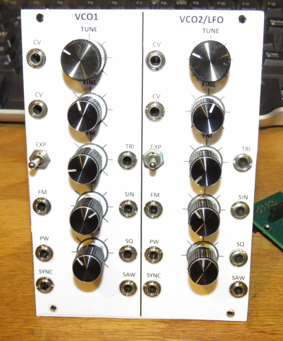
Dual VCO front view
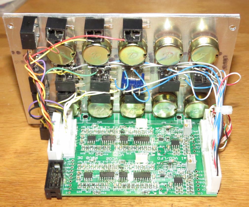
Dual VCO rear view, with lots of hand wired components.
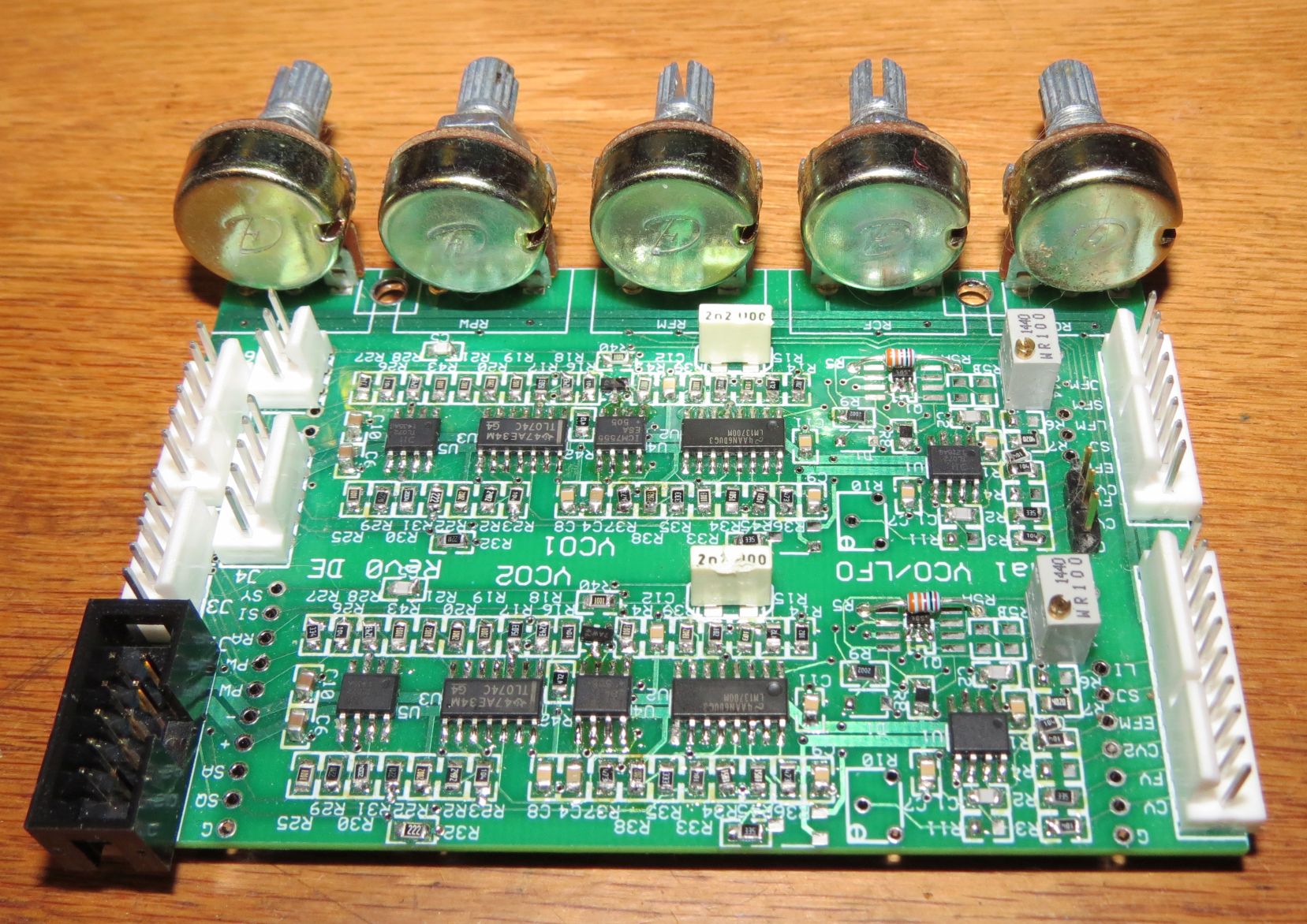
Dual VCO PC board
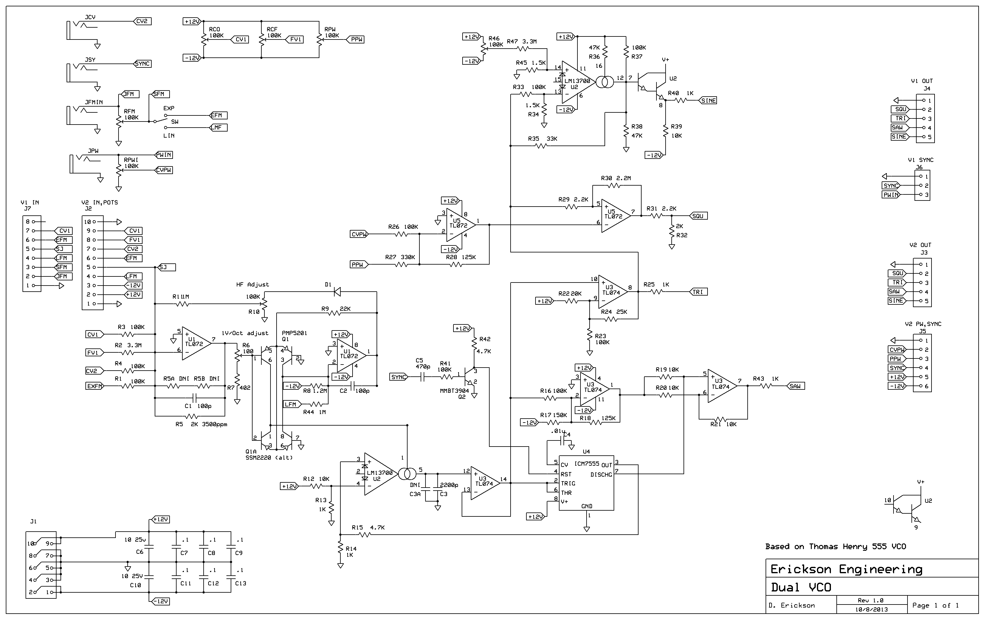
One channel of Dual VCO Schematic
MIDI to CV
Like most synths, I
needed a keyboard interface. After investigating Arduino and other
DIY Midi projects, and due to my lack of Midi experience, I
decided to buy, not build, at least as a start. I bought the
HexInverter Midi2CV converter kit ($120) and in one evening of
soldering, had it working. This is a nice unit with accurate and
easy to calibrate DACs. With a couple of Vector rack rails, I
built up a first Eurorack system. Bought a Synthrotek Eurorack
power board on Ebay and connected it to a dual +/- 12V lab supply.
Finally I can play a tune, woohoo!
I like that the Midi2CV has 4 note poly-synth mode, but 2 note or
3 note poly-synth would be useful too. I can foresee new modes in
the future. HexInverter provides source code that runs on the
Microchip Pic processor, so maybe modify it. This is an
interesting area to play with. I like the idea of using an Arduino
processor... So many possibilities...
Output Precision
The voltage outputs of
the MIDI2CV are quite accurate and operate from 0 V to
8.00V, 9 octave range. However, there is an output
protection resistor of 220 ohms on each CV output. This causes a
slight error of -.2% in voltage when a 100K VCO load is applied.
The bad news is that when you drive multiple loads, each load
causes an additional -.2% error. At high frequencies, this error
is a larger pitch error. Say 1% of 8V is -80mV. at 1V per octave,
an error of a full semitone. Since I use my MIDI2CV regularly to
calibrate and test VCOs, and to drive multiple VCOs and filters,
and possibly other stuff as well, I plan to address this
error. An external precision buffered multiple would address
this, but even it will have some input load. There are a couple of
ways to address this. The resistor is there to limit the current
output in the case of a short circuit. Just plugging in a cable to
a jack causes a momentary short to ground as the tip of the plug
slides past the ground ring of the jack. If you were to mistakenly
partially plug one in, a short circuit could be present for a long
time. The CA3140 op-amps specify a maximum short circuit output
current as about 50mA so the power dissipated in the op-amp during
a direct short to ground is about 12V x .05A = .6W, quite hot for
a plastic 8 pin DIP package. The 220 ohm resistor reduces this
power by about 1/2, a safer value. Like many op-amps, the CA3140
is specified to drive a short to ground or to either supply
voltage continuously without damage. So I may just replace the 220
ohm resistor with a short circuit. If I do this I'll have a few
spare CA3140s around in case they get damaged.
A more elegant solution is to take the feedback of the circuit
from the output of the 220 ohm resistor instead of the output of
the op-amp. This way, voltage drop across the resistor is
compensated for. This requires cutting the traces to the wipers of
the gain trimmers and adding 4 wires. Then because the 220
ohm R and any cable capacitance forms an additional high frequency
pole to the feedback, an additional compensating capacitor may be
needed from the op-amp output to the - input. Cable has about
10-20pF per foot, and maybe 10 feet of cable to multiple
loads, so about 200pF of capacitance worst case. I should be
able to apply, say a 470pF cap to the output and test the step
response. Then add compensation if there is excess
overshoot, ringing, or oscillation.
As a shortcut you could apply this fix only on the main
output, CVA and then make sure to use this one for heavily
loaded or precision patches.
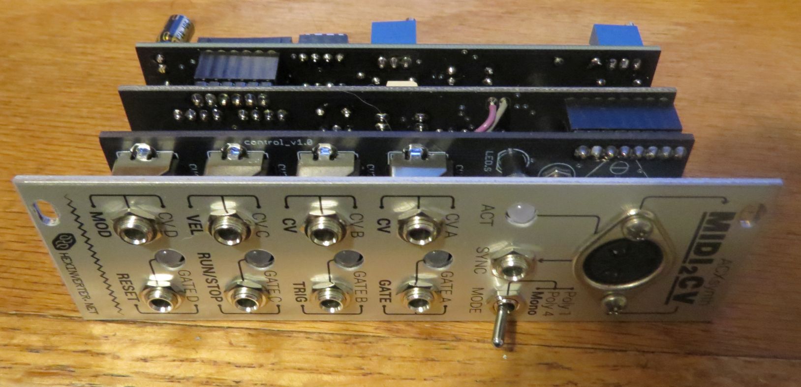
MIDI2CV, built from a kit from HexInverter
Sequencer
My keyboard skills are
limited to say the least, and I wanted a way to play simple
sequences automatically, without having to hit keys. So I
investigated sequencer circuits, initially just as a test
generator. I like the old SimpleSeq from Hexinverter. Their clever
circuit uses a 3 way toggle switch per note. The 3-way switch
positions are ON, OFF and Loop, allowing the sequence to be set
from 1 to 8 notes and to skip any notes. The clever part is that
diodes connected to the pots and switches control the analog
output, gate, and reset. I cut a front panel and wired it up.
Again, lots of hand wiring, I built the first one using eight old
10 turn pots I had lying around. This was a mistake since the 10
turn pots don't have an indication of the note settings. I rebuilt
it with smaller 16mm single- turn pots with indicator knobs, which
work better, and are smaller and cheaper. Again, lots of hand
wiring. This really needs a PC board. I built a second panel
with smaller one-turn pots. It is a work in process.
For its gate output, it occurs to me that having a variable width
output would be useful. Most sequencers use a variable clock
frequency and a fixed 50% duty cycle. It's a bit tricky to
build an oscillator with independent frequency and duty cycle
outputs. I picture a triangle oscillator and a variable threshold
to set the duty cycle. Someday...
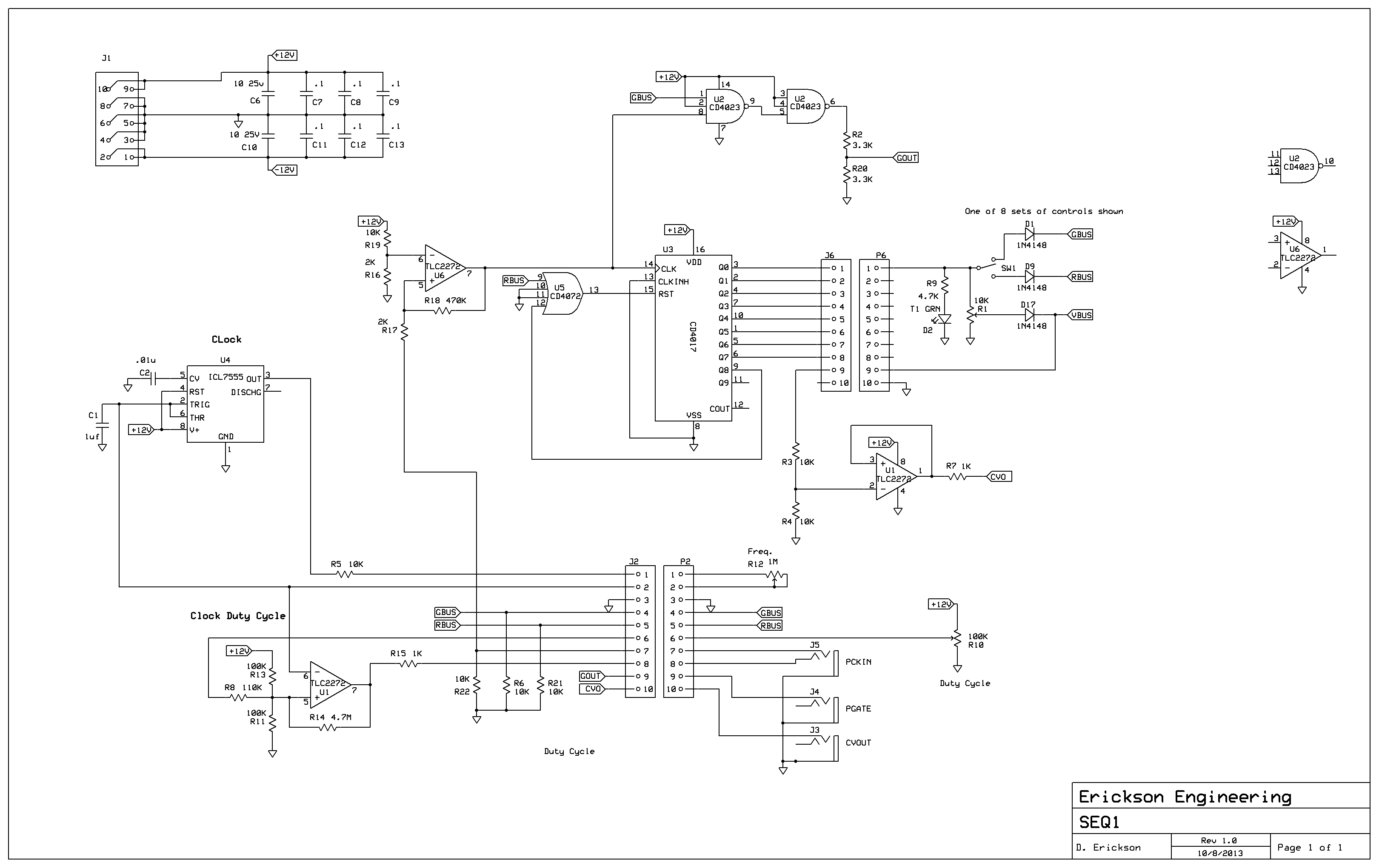
Here is the current sequencer schematic, a work in progress. One
interesting bug I found. At first I used an ICM7555 for the clock.
The circuit regularly skipped notes in the sequence. It turns out
that the 7555 output occasionally had glitches on one edge
transition, maybe when operating at slower clock speeds. I tried
lots of grounding and bypassing tricks, but couldn't stop it. I
substituted it with a TLC555 from TI, and no glitches. So this
circuit works better with the TLC555 and the VCO is
more precise with the 7555. Well, Professor Eaton at WPI in 1976
warned me against using '555 timers, and I generally heed this
advice. However they are particularly appealing for quick
and-dirty synth circuits. Let the designer beware...
VCA
I needed a VCA right away
to take the keyboard gate signal and vary the output of a VCO.
Since I don't know whether linear or exponential is best, I found
a Ray Wilson (MFOS) circuit that does both. I built it up on a
solder-less breadboard and am still using it this way. I have a
board design for a dual VCA but haven't built it yet. My
first VCA used the 5V gate signal as its control. It works, but
only does fast attack and decay. While it is better than nothing,
I need an ADSR!
VCF
I ordered the bare boards
and hard-to-get parts for the MST
VC-LPF kit from Synthrotek. I like these guys since they
also have 3.5mm jacks and 9mm pots for good prices. I had many of
the parts on hand so it was a low cost project. It is quite
flexible, having a fixed 1V/Octave input as well as inputs and
controls for frequency and resonance. It has 12dB and 24dB per
octave outputs. I like it and it works well. My only complaint
about MST kits is that they do not provide a schematic. All kits
should provide schematics, not only to allow one to mess with the
design, but also to allow troubleshooting it if it doesn't work
right away. A lot can go wrong when building a kit.
ADSR
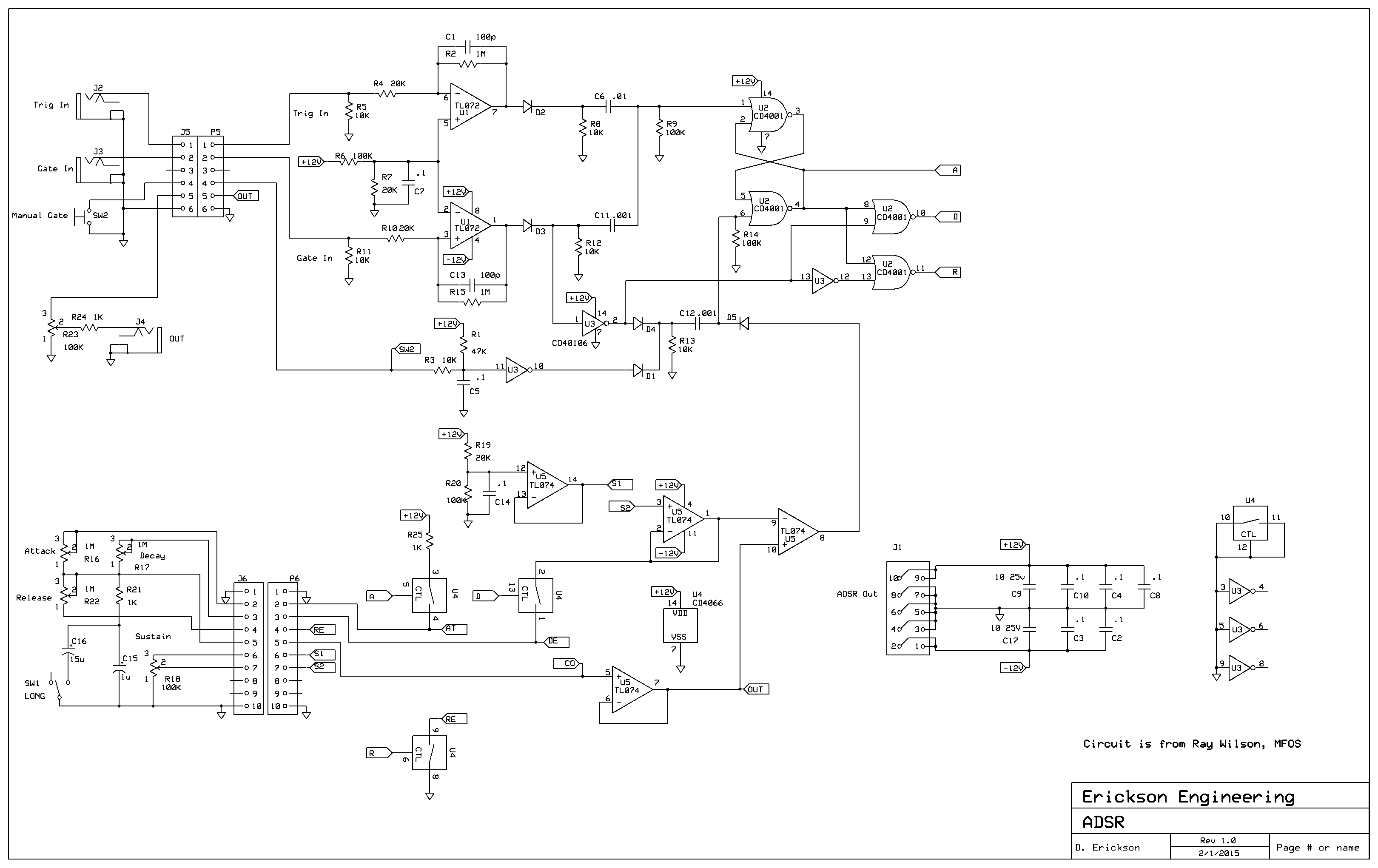
I chose the circuit from
Music from Outer Space (MFOS) by Ray Wilson. Their boards are not
Eurorack, and I wanted a few of these, so I laid out a PC module
with two parallel boards. With an ExpressPCB mini board (3.8" x
2.5") I built a front panel board and a circuitry board, each
about 1.2 x 3.8", and then cut the two boards apart lengthwise.
This worked out pretty well.
But when I built them up, They would work sometimes, and not
others. I checked out the circuit, and discovered that the TL074
op-amp was getting hot when it stopped working. This corresponded
to an increase in the -12V power supply current to the system.
Turned out that the CMOS 4066B switch doesn't like any negative
voltage on its input pins, and would latch-up. This only occurred
when the -12V supply came up at the same time or before the +12V.
My system, like many Euroracks, uses similar + and - 12V supplies,
and since the negative supply is generally less loaded than the +,
it comes up a millisecond or so before the plus. You could make it
occur or not occur by plugging in the 10 pin power connector to
the ADSR tilted towards the + or the - end first. I sent Ray
Wilson a note with this problem, and he said that hundreds of his
ADSRs have been built without any reports of this bug. I suspect
it may be due to the specific 4066B manufacturer parts that I used
vs. the ones he uses. I fixed the problem by changing the TL074 to
a +12V CMOS single supply part. This required a cut and jump on
the opamp's - supply pin. It works fine this way and I have built
3 of these so far.All three failed when I used the original
TL074. In general, circuits that use multiple sourced parts
should not depend on a specific manufacturer's part.
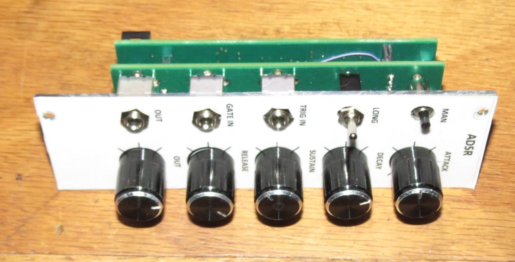
Here are some shots of the ADSR board. Note the stacked board
construction, the use of Earthernvar 3.5mm jacks, and 9mm Pots. No
hand wiring, Yay!
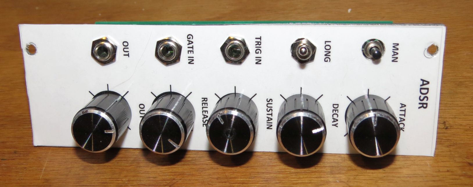
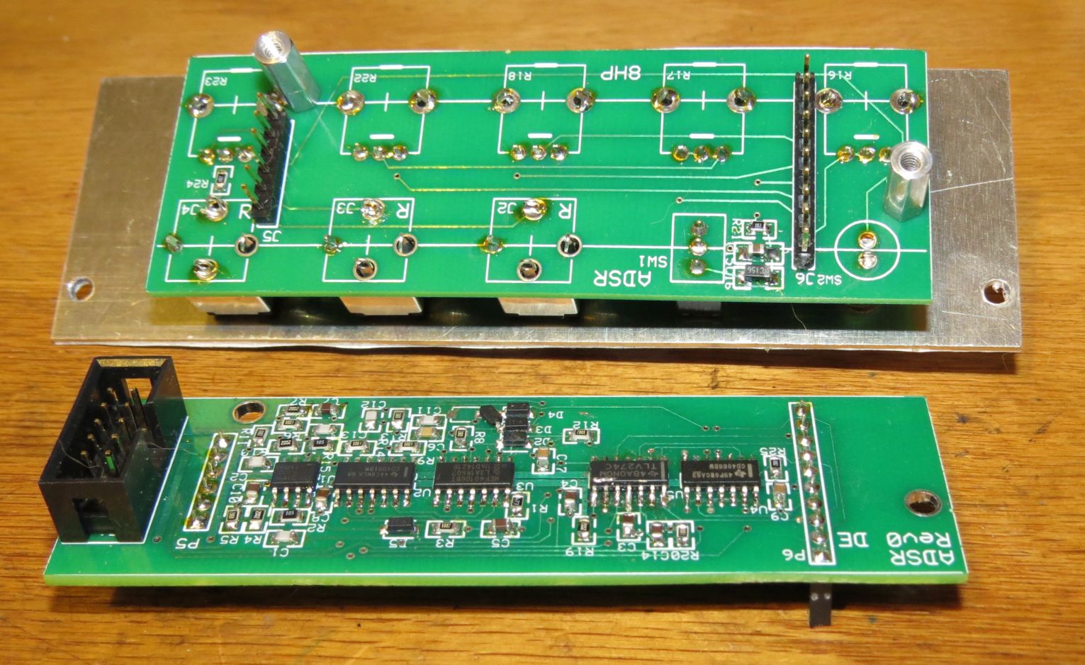
The board is an ExpressPCB mini, sliced down the middle to make
the two boards. PCBs for 3 ADSRs for $80, not bad.
Building Front Panels
Most Synth builders use
6061 grade Aluminum, 0.062" thick for front panels. At first I
would mark it out and cut it on a band-saw with a fine-tooth
bi-metal blade, and file the edges smoother. Then I discovered a
100 tooth carbide table saw blade for soft metal, $25 on Amazon.
Now I can cut panels faster, smoother, and more accurately. I lay
out the panels with Visio Technical, which has decent measuring
and marking tools. Any other 2D CAD tool would work. The saw blade
throws vast amount of metal chips, so good eye and clothing
protection are a must when cutting. I use either a
tri-square with a 1/100th inch scale, or my digital height and
marking gauge. The height gauge is a great tool for doing
precision work for about $30. Simply set the height gauge to the
dimension from the edge that you want, hold the panel vertically
on a flat surface, and use the height gauge to scribe a line at
the dimension you want.
For labels, I use laser printed paper and a low cost laminating
machine with 3mil pouches. Then contact cement the label to the
panel, sighting the holes and outline through a bright light. Once
you cement the overlay to the panel, cutting the label outline and
the holes with a sharp Exacto knife is easy.
You can also just tape a paper template to the metal and
center-punch the holes through the paper. This is a bit less
accurate but is quick and easy for building one panel. When
drilling, I start with all 1/8" holes and then enlarge the holes
with the appropriate bits. If you are making 3/8" or larger, it is
best to make the next-to-last hole just a bit smaller than the
final. the 1/3 - 2/3 - 3/3 rule works well to reduce burrs. Start
with a bit about 1/3 of the final size, then drill 2/3, then the
final size. This only takes a minute longer to change bits, and
does a nice job on soft aluminum.
Another trick for building more than one panel, is to mark and
drill all the 1/8" pilot holes on one panel, then use that as a
drill guide to build more. It's a good idea to use a thicker metal
like 1/8" or more for the guide, depending on how many you plan to
build. This requires a way to keep the drill guide and the panel
perfectly aligned during drilling or errors will accumulate. You
can use screws and nuts, or clamps. I haven't perfected this yet.
Current Status,
October 2015
So now my Eurorack system
can play some decent sounds. It consists of:
- One Rack, Homemade
chassis, Vector rails and Synthrotek Power Board
- Midi2CV ,
Hexinverter kit
- Dual VCO, modified
Thomas Henry design, my PCB
- Sequencer,
half-built, based on SimpleSeq from HexInverter
- VCA, still on a
solderless breadboard, based on MFOS VCA
- ADSR, MFOS ADSR, but
my PCB layouts
- VC-LPF, Synthrotek
- Passive mixer: Just
jacks and 100K resistors
- Power Supply. I'm
still using a dual lab supply to power this.
What's Next? The plan is
to add a second and someday a third rack and fill it with these
modules:
- Sequencer: Wire up
all the gate logic and design a variable width gate. Maybe
bring out all the individual outputs to drive a drum machine.
- Dual VCA board,
constructed like the ADSR on an ExpressPCB mini board, cut in
half
- Noise Source, maybe
a random sequencer like Turing Machine
- Two more VCO/LFOs:
another dual just like the other
- Proper Mixer with
amplifiers.
- Full function
filter: High, Low and Band-pass
- Copy of the Moog
Ladder filter? I Want to see what the magic is all about.
- Play with advanced
Midi2CV features like keyboard split, polysynth...
11/1/15
Prototyping and
Design:
In building boards, I use
a mix of prototyping, simulation, and design analysis. For
simulation, I mostly use Linear Technology's excellent
LTSpice. At various web sites, I found spice models for
commonly used synthesizer parts such as TL074, LM13700, and 555s.
Based on these models I am able to simulate the VCO, VCA, and
VCFs. Follow this link for a .zip file containing these spice
models. Unzip the files, install LTSpice, and open the .asc files.
Then you can simulate the time and frequency domain circuits.
A warning though, precision circuits that require low offset
voltages, good matching, tight gain control, etc., all simulate
wonderfully, but the reality is that transistors don't match,
amplifiers have offsets, and gains (particularly the LM13700) vary
from part-to-part. This is the reason there are so many trimpots
in synthesizer circuits.
For prototyping, I use solderless breadboards. These perform
nicely for low frequency analog designs like those used in
synthesizers. I built up a small bracket to hold a few 3.5mm jacks
and potentiometers for convenience and reliability.
Mixer
You've got to have a
mixer or two. Or more. Ideally you should mix VCOs or other sound
sources together before filtering and VCA-ing. This is a key
capability of the Moog Mini and the Arp, and allows you to turn
knobs instead of moving cables. Then if you have multiple
voices, you will want to select them individually or mix
them together. A utility mixer for control voltages is
useful too. I wired up a simple passive, fixed gain mixer: four
inputs wired to 100K resistors, and a couple of outputs.
This worked, but is not at all flexible.
While I was contemplating a mixer design and looking at various
commercial ones, I came across Synthrotek's
MST 4 Input Audio / CV mixer. It is DC coupled and works
with CV's as well as audio. It has a switch per input, handy to
isolate signals without having to adjust and readjust knobs. It
has an inverted output, also handy for processing control
voltages. An inverted LFO ramp sounds very different from the
non-inverted ramp. Same with ADSRs. It has overload LEDs, too.
Also a jumper-able x1 / x2 gain. Best of all, the PC boards and
front panel cost a mere $25. It is a very simple, one IC design
and I had the other parts in stock: resistors, caps, TL074,
connectors, pots and switches. Built it in an hour and it works
very well.
My only complaint is that I prefer screws and spacers to superglue
for holding the boards together. And since the connectors
between the board are symmetrical, it is easy to connect the
boards backwards. As usual, keep the power connector on the
bottom. And of course my usual complaint that Synthrotek doesn't
provide schematics for kits. In this case the design is so simple
to reverse-engineer that it seems just an inconvenience to not
publish a schematic. Wait, that's 3 complaints.
Update: 12/7/15
I bought a second MST mixer and they have added holes for board
spacers. Kudos! I may drill holes in my first unit to add
spacers.
Case: Rev2
I have pretty much filled
up the first 19" case, and foresee filing another with a couple of
VCOs, VCAs, a better sequencer, not to mention some cool
commercial modules. Three 19" racks should last me a few years.
Plan A was to buy or build 3U rack sides, but I don't really want
to mount it in a 19" rack. Instead wooden sides for now, maybe a
handle on top, designed for small size and portability. I
don't have any other rack stuff, so wood it is. Since this will
regularly sit behind
That means the rack sides should be simple metal strips to hold
the Vector rails. These will have a couple of holes so they can be
screwed into the wooden sides. A few caveats though: First, you
need to remove most the modules to access the screws. I don't
foresee removing the racks many times, but I may eat those
words. Next, Power distribution boards need separate
mounting. To ease the pain, I plan to use a single board
(Synthrotek, but apparently obsolete??) with 17 16 pin connectors,
located between the two 3U racks so the cables can reach modules
in 2 racks. Finally, I discovered that the screws that mount the
rack to the wood need to be flat heads and countersunk. Pan head
screws interfered with some modules.
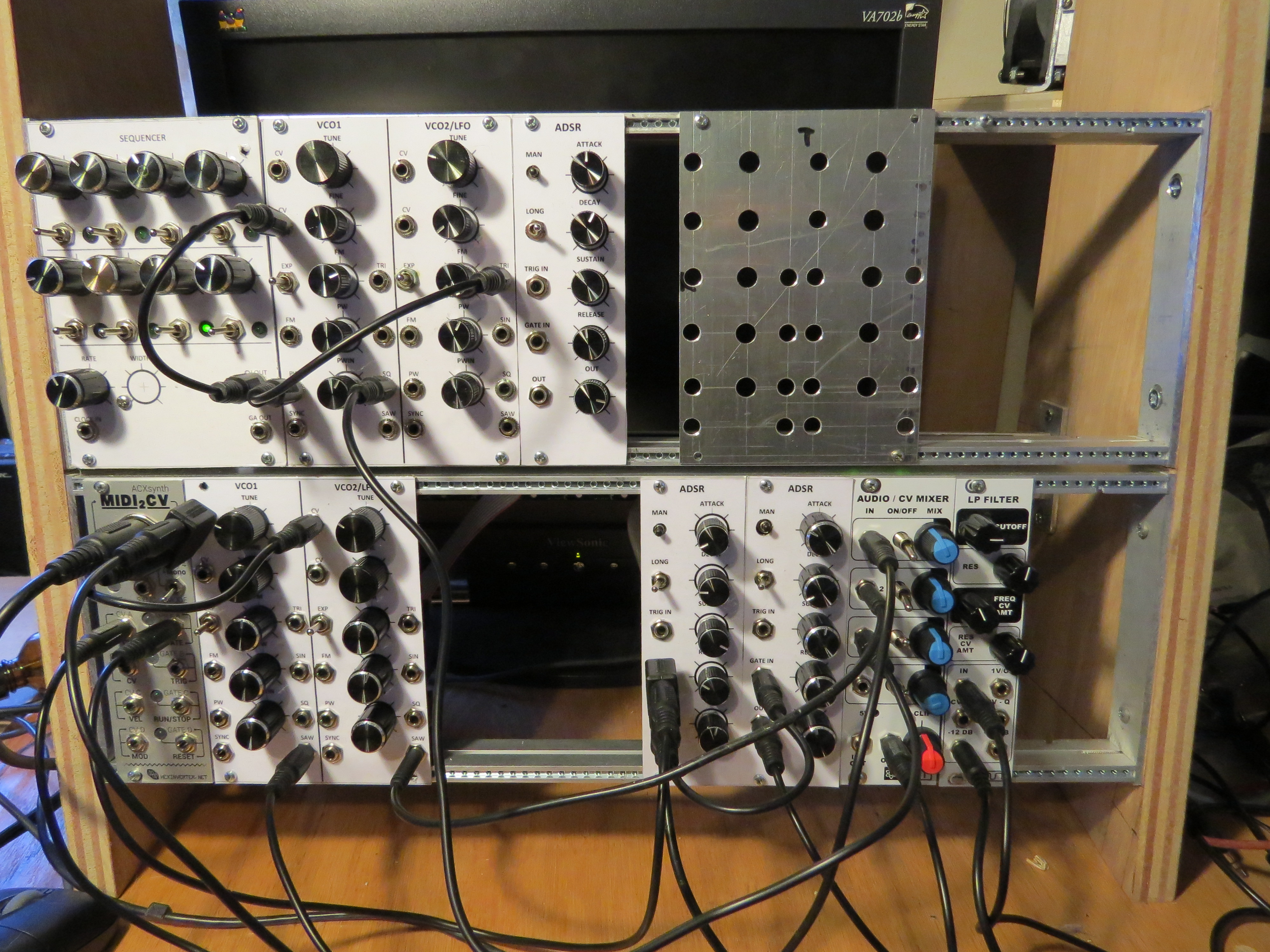
Here it is new rack. The power distribution board is obscured
behind the center rails. Note the new Synthrotek Mixer. I
built up the second Dual VCO this weekend. The blank panel
will be the third VCO, someday. Even with the Dual VCO PC
board 99% built, it took about 7 hours to machine the panel and
hand wire the 18 jacks, 2 switches, and 5 pots. Still have
only the one proto-board VCA, off screen. That's next.
Update 11/15/15
I went a little crazy
this weekend. While waiting for the Dual VCA boards to show up,
and on a rainy cold Sunday, I took apart the new case, added the
power supply, a bit of sanding, and a coat of polyurethane.
Then I finished the prototype sequencer, something that was on the
list for months. The mode switches that control the reset and
enable had not been connected to logic. The clock output had not
been wired up, and the control voltage out was hard-wired (hacked)
to the pots, and not buffered. All these are now addressed and I
updated the schematic above.
Last week I went to a synth show at "La Labratoire" near Kendall
Square. Great show with two synth performers, and one performer
who made music all from sampled sounds. On the way I stopped at
Steve's to play with his stuff. Steve loves the Turing Machine
random sequencer. I had ordered the bare board and had some of the
parts. While I was ordering the DAC0800 and other parts, I
figured, why not get another Synthrotek module, the MST Sample and
Hold / Noise.. And heck, while I'm there might just pick up the
DS-M drum machine I've been lusting after. Think of all the money
I'll save in shipping buying two mods at the same time. So now I
have 3 Dual VCAs, a Turing machine, a sample and hold and a
drum machine all in process. Yikes! Gonna be a fun thanksgiving!
As they say on Muffwiggler, "I'm not an addict, I can quit any
time."
Dual VCA
Finally the VCA boards
arrived and I built up the first one. The linear gain control
works fine, but I got no output in Exponential mode. After a bit
of debug, I found that I had bought the wrong matched PNPs. There
are two versions of the DMMT3606 and I bought the wrong one.
Worse, the only matched 2N3906 in a SOT23 case has the bases in
common, not OK for an exponential source, and the correct part
only comes in a SOT363, which is the tiny package of the PN5201s.
I need to re-lay out the VCA and VCO to use this tiny package. I
hate to use such a fine-pitch part. Sorry.
The initial output waveform of the VCA was a bit distorted. When
10V p-p (+/- 5V) triangle input was applied, there is too much
curve on the slopes of the triangle (PHOTO!!). This is from
overdriving the low-voltage inputs of the LM13700 with a 25K/500
ohm 50:1 divider, so +/- 100mV at the inputs. They are only linear
to about +/- 50mV or less. A 100:1 divider worked well.
I am getting better and quicker at building panels. With careful
setup, the table saw is able to hold about 10 mils accuracy on
three panels. Then I was able to mark one panel, drill all the
holes to 1/8", then clamp all 3 panels together and using the
first one as a template, drill the other two to 1/8". Then it is a
simple matter to enlarge all the holes to 1/4", the jack and
switch size, then enlarge the Pot holes to 5/16". All 3 panels
came out perfect, and in record time.
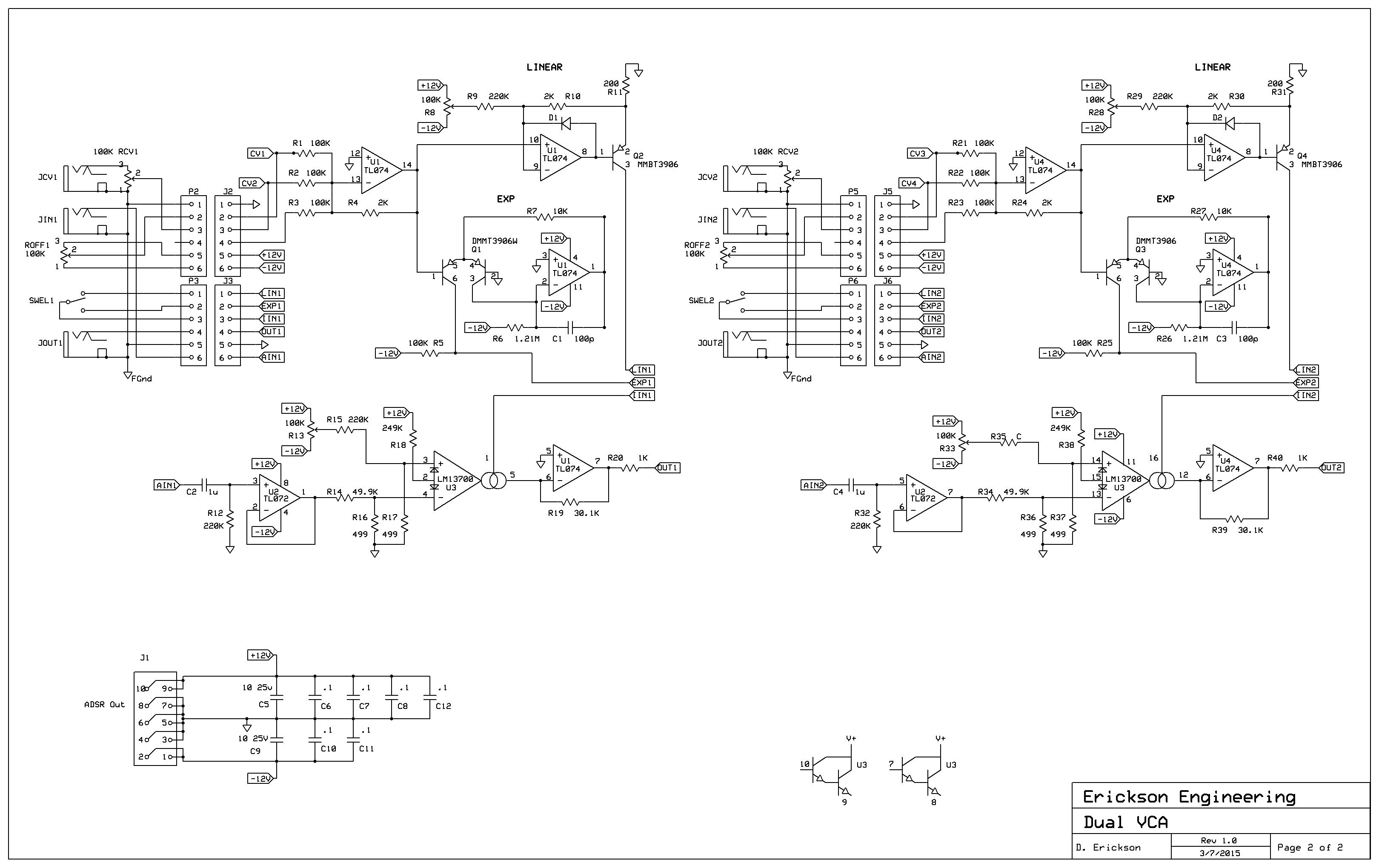
Here is the Dual VCA schematic. On my first board I installed no
trimpots and it works well, but I have not tested the important
parameter of feed-through. When the audio input is 0, and the
control voltage changes, there should be no output glitch. This is
what R13 and R33 are for. I'll let you know.
Synthrotek MST Noise /
Sample and Hold
The board and panel
arrived and I built this up. It works well as a random CV
generator. No output level adjust, so your inputs may needs a
level adjust. I found that the S/H input has a low 1K input
impedance. Since most CV outs have about 1K output impedance, you
will lose about 1/2 of the CV signal and any other CV inputs that
you also send to will lose signal. There is a spare op-amp on the
board that could have been used as an input buffer, so I'm not
sure why MST did it this way. I may modify it to use the spare
opamp. The board works well as a noise source and as a
Sample and hold.
Synthrotek DS-M Drum
Machine
I built this one up also.
It is based loosely on the widely cloned Coron DS-8 drum design.
Pretty happy with the way it works. It uses the trigger input and
a front panel pot to determine the drum amplitude as well as the
noise time, sweep time, etc. So the trigger input pulse width has
a strong effect on the drum sound. See, I knew it would be
important to have a duty cycle control on my sequencer clock
output. It makes an acceptable tom or bass drum. I haven't found
good snare or hi-hat settings yet. Now I could really use the
Turing Machine with Pulses output. Soon...
I saw some high-frequency oscillation on the bottom of the
triangle wave output. The output amplifier of th DS-M consists of
an LM13700 VCA stage feeding an LM324 with a 510K feedback
resistor. The LM13700 output adds a bit of
capacitance, and so the 510K resistor causes a 'pole' in the
response and marginal instability. I changed the LM324 opamp
to a TL074 and this caused the oscillation to go away, but the
correct fix is probably to add a 10-22pF compensating cap across
the 510K resistor. Changing all the opamps from LM324s to TL074s
seems to work fine.
Turing Machine Random
Sequencer
I am so impressed with
the simple Turing Machine sequencer design and the amazing range
of sounds it is capable of. Consisting of a simple 16 bit shift
register, a noise generator, 2 switches, a knob and wow!
Steve uses one with the optional Voltages and Pulses Expanders as
his main sequencer. He uses Pulses to drive drum machines. I need
to get one. The 4 boards and panels are reasonably priced on
at $120 on Synthcube. Speaking of which, Synthcube, where have you
been all my life! They offer hundreds of DIY kits, boards and
panels. Yikes! I am waiting for a couple of the main boards from
Thonk for cheap, but have also ordered the full set of 4 PC boards
and 3 panels from Synthcube since I really like their panels and
want at least the Pulses Expander.
The first board arrived from Thonk. I had ordered parts for it so
was able to build the board in a couple of hours. It worked right
away. Glad I ordered the other boards and front panels.
Then the other boards and panels arived. The expander and Pulses
modules are no-brainers. Very simple and low parts cost. Voltages
uses 8 Alpha slide pots with cute LEDs, but these are only $2.50
each from Mouser.
As usual, I am the bug finder! In looking at the Turing
machine schematic. I see that the designer built an XOR gate the
hardest way possible: using two transistors and two transmission
gates. And I spied the usual bug: An op-amp operating from +/-
12V feeding CMOS running from +12V. Sure enough, the op-amp
gets very warm when outputting - voltage, due to the CMOS
protection diode. At least it doesn't latch up and die like the
MFOS ADSR did. A simple series diode and a resistor to ground
addresses this. People, please don't do this.
It is still not working 100%. I accidentally ordered the SMT
version of the 4015 shift registers. And the ancient ones I had
since the early 80's don't like driving the LEDs, so they fail
after a few hours. New parts should fix this.
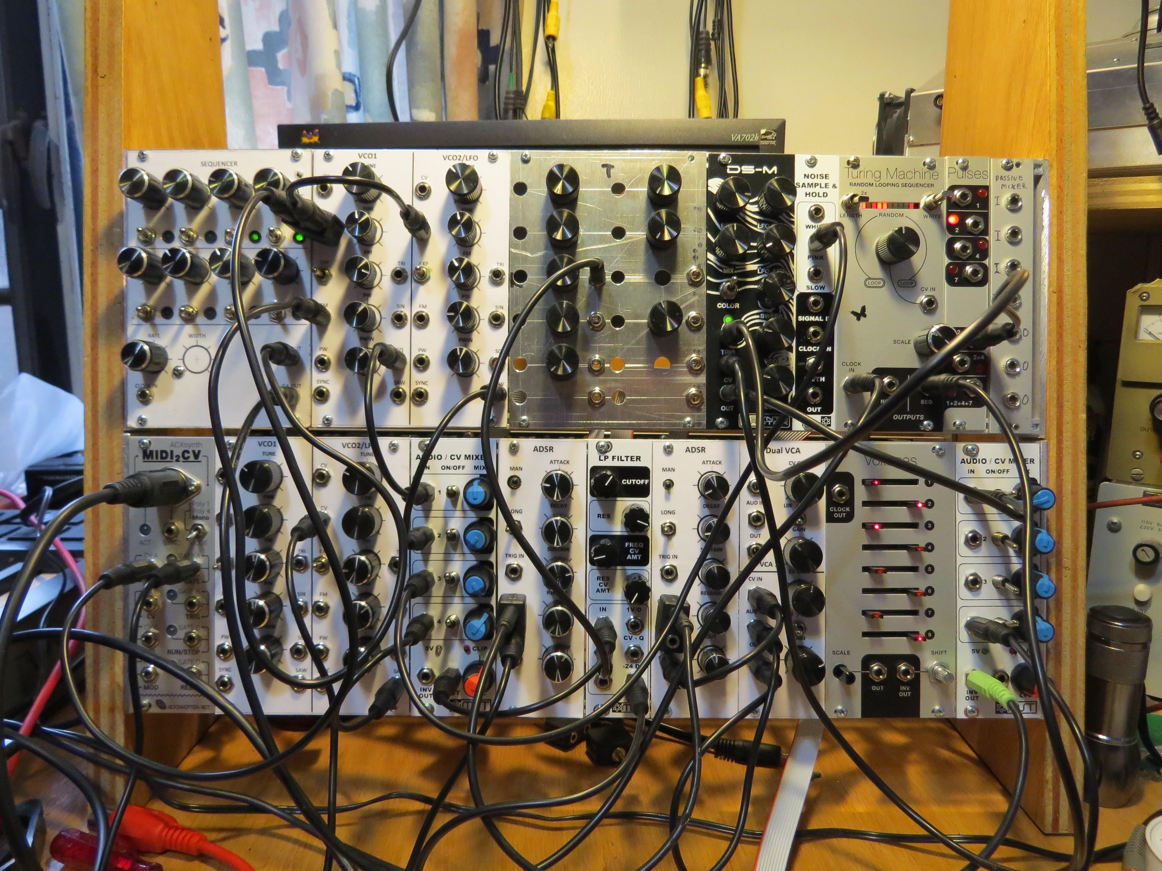
Here is my baby with 2 racks full. Time for the third rack and a
second power board.
Power supply
With all the new modules,
my power supply is drooping a bit. The problem appears as annoying
120Hz FM on the VCO outputs. I used a +/- 12V adjustable linear
board I bought on Ebay. I feed it with a 2x12VAC 1.5A transformer,
but 12VAC is not enough to prevent droop at currents of 0.5A. I
could use a 15VAC transformer, but then I would be dropping
several volts more across the regulators. Ideally it would
be 13VAC or 14 VAC per side, not common voltages. Time for a
switcher.
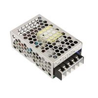
I had some old DC-DC boards at work and modified an obsolete one
to convert +12V to -12V. For the +12V I use the amazingly small
and fully enclosed TDK-Lambda LS25-12, 12V at 2.1A, $20 at
Digikey. Works swell.
Synth Kit and DIY
Building Tips
It occurs to me that
non-EE synth people may struggle with building kits. It is
pretty straightforward if you have some basic tools and supplies.
Start with a simple kit such as the MST 4 Channel Mixer to build
your skills and confidence. Here are the basic tools, which are
good to have around for any electronics fun:
- A decent temperature
controlled soldering iron with 0.060" chisel tip and 0.020" or
0.025" lead solder
- Nice needle-nose
pliers, diagonal cutters and wire stripper
- Nut-drivers for the
front panel jack and pot nuts, typically 5/16" and a 10mm deep
socket
- A bin of plastic
drawers to keep parts in
- Illuminated
magnifier
- SolderWick size 1
and 2
- Good fine tweezers
- Cheap ribbon cable
crimp tool
The kits I build use a
lot of the same parts over and over, so having a stock of the
basics is good. You can build this stock up for about $100:
- DIP ICs, a few of
each: LM13700, TL072, TL074, LM324
- Transistors: 2N3904,
2N3906
- Resistor 1/4W 5%
assortment: 5 or 10 of the common values, check on Ebay and
Amazon
- Resistor 1/4W 5% in
multiples of x1.00, x2.00, x4.99, values from 1.00K to 1.00M.
Buy 50 each of the 1.00 values and 20 of the others. You
can always use a 1% in place of a 5%
- Ceramic caps,
radial, 50V, 0.2" lead spacing, 100p, 1000p, .01u, .1u,
- Electrolytic caps
10uf 25V, radial, < 0.3" high
- DIP IC sockets,
8/14/16 pins
- Synthrotek or
Earthenvar vertical 3.5mm jacks and hex nuts, a bag of 50 will
get you started
- 9mm knurled shaft
pots, Linear taper, 50K, lots of 100K, 1M
- SPDT toggle
switches, ON-ON, ON-OFF-ON
- 16mm knurled shaft
pots, 100K and 1M for hand-built stuff
- 5, 6 and 10 pin
single row female headers, 0.1", gold
- Break-apart male
headers, 0.1", single and dual row, gold
- 10 pin Box headers
for Eurorack power
- 10 and 16 pin ribbon
cable connectors and 10 pin ribbon cable if you build
your own power cables.
Then when I build a
kit, I go through the BOM and my stock to see what parts are
missing and do a Mouser or Digikey order for the missing ones.
As I build a board, I print the BOM and mark any components that
I am running low on. I generally keep an open shopping cart on
Digikey.com. If you go back and touch the cart once a week or
so, it seems to stay there. If you're worried about your cart
disappearing before you check out, just print out a copy.
Of course you'll need
synth cables and adapters:
- 6", 12", 18", 24",
3.5mm mono or stereo patch cables
- 2:1 adapters
- 3.5mm to 1/4"
adapters or cables.
For hardware and
panels:
- M2.5 x 6mm screws
for Eurorack
- 4/40 x 7/16"
or 11mm standoffs
For building panels:
- 6061 aluminum,
0.062"
- 100 tooth soft-metal
carbide 10" blade (Amazon)
- Table saw for above
- Mill files
- 1/8" Drill bits
- 1/4" Drill bits
- 5/16" Drill bits
- Exacto Knife
- 3 mil Laminator
pouches and a low cost Laminator
- DAP Contact Cement
To build SMT boards:
- Same ICs, resistors
and cap values as above, but 0.050" pitch ICs and 0805
discretes
Surface Mount (SMT)
Building Tips
If you would like to get
started building SMT boards, my ADSR and VCA are probably a good
place to begin. Install ExpressPCB,
and then open the .zip file,
and you can click on any .SCH or .PCB file. Once you open a .PCB
file, you can order boards directly. While the boards are being
fabricated, open the BOM and order the SMT parts from Digikey or
Mouser, and the front panel parts from Earthernvar or Synthrotek.
When the boards arrive, you'll need to cut them apart with a band
saw, jig saw, or hack saw. Use a bi-metal blade for FR4 PCB
material. File the edges smooth.
To solder SMT, add a small dot of solder to only one pad of each
component footprint on the board. While melting the dot, place the
component on the and align with tweezers. Then go back and
re-solder the other pad(s). Clean up shorts or blobs with
solderwick. Clean the boards with Flux-Off or alcohol based
cleaner. For good soldering instructions, see EEVBLOG #180
on Youtube. Dave has an excellent 3 part soldering tutorial
there.
Page
2: the Digital part
Dave's Home Page
Last Updated: 7/8/2017


